


Tom
-
Posts
253 -
Joined
-
Last visited
Posts posted by Tom
-
-
2 hours ago, And said:
What about EIRP? Perhaps this calculator could be made fairer and help to calculate it instead of the user, ie the calculation changes dBm instead of EIRP. And how far does it make sense to have horns with a different gain if the whole end is leveled at the transmitter's TX power to comply with EIRP?
In this sense, I can take any, 5 gain, 15 gain, everything in the end will be equal to for example 30-36 EIRP (possible MCS has any requirements) 30 = Gain-TXpower.
Thanks for the tips, we'll look into it in our future updates
-
That is interesting, and how exactly do those WISPs identify that the radio works in MU-MIMO besides the grouping of the CPEs? Regarding the bracket suggestion, maybe in the future we'll make what you suggest, thanks for the tip..
-
BE is important for both AP and CPE, but more so for AP (from the angle of a network as a whole), since AP is the device to which all the CPEs are connected. So if the AP radio is seeing a lot of noise, all CPEs suffer. Where as if only one CPE sees noise, it's only that one user that sees the effect..
In my opinion BE says much more about colocation capability than FTB ratio - one side lobe (back lobe) simply cannot be more important than all the other side lobes combined.
-
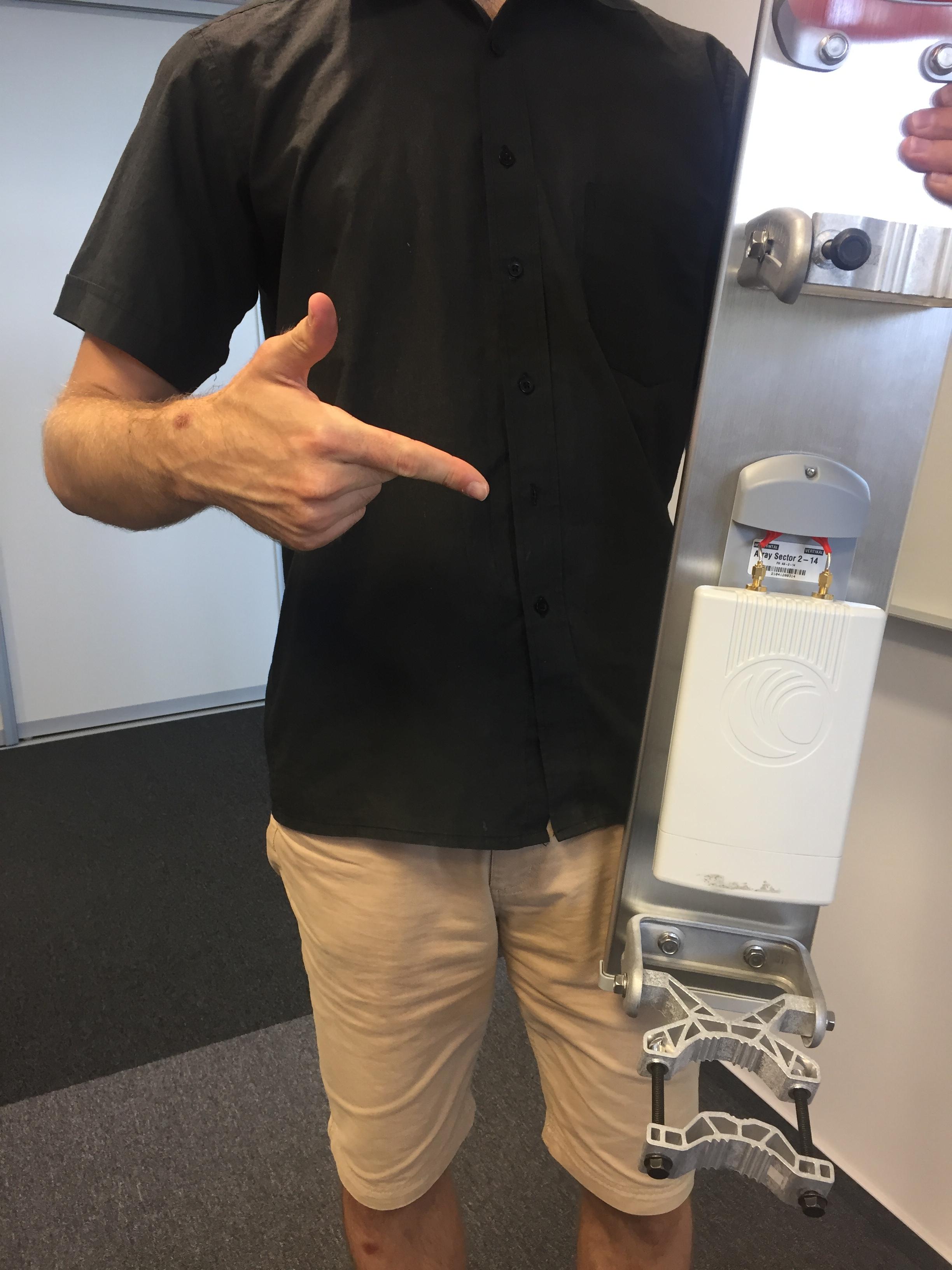
ok, so we synthesized the real install for you check out the photos :)


-
Unfortunately we don't have many photos of the AS-5-20 with this radio, why are you so keen on seeing real life picture?
We could print it out here and test it if you want, but it's a simple plastic part and our designers have tested it long time ago
")
-
I don't know do we have a real install photo of this setup but if you search facebook WISP channels, maybe you'll get lucky
-
Yes, the ePMP 3000 MU-MIMO works if the antennas have horizontal spacing, without it, it won't work. They can be somewhat vertically spaced, but the horizontal spacing or lack there of makes it or brakes it.
It has to do with the radiation pattern of the array - if the antennas are above each other the coverage of the array looks almost identical as if you used just one antenna (except the further reach because of the array effect). Once the antennas are horizontally spaced, the coverage you see shows minima and maxima depending on the antenna spacing, that result in the possibility of 'spatial filtering' and polarization division into 2 user groups and therefore MU-MIMO.
In the near future we will release a video about this, so stay tuned to our YT channel and SM outlets..
-
11 hours ago, And said:
I find it strange that antennas with such an FBI rating can be assigned a class carrier.
The question of why this is important also seems strange, but perhaps it was meant differently.
Smaller FBI, more noise. It probably doesn't affect that much if everyone on the mast is horn, but in the case of a hybrid, it makes more noise than if there were no horn. Noise is the biggest invisible enemy.Right, the higher FtB ratio the less noise. But, FtB ratio quantifies only the backlobe - one side lobe out of many antennas used in WISP industry typically have and all that at one frequency and from a single polar plot.. What about the rest of the radiation pattern? The rest of the sidelobes are much substantial than just backlobe by itself.
This is exactly why FtB ratio is practically useless (in other words useful in very few instances). We believe Beam Efficiency (BE) is way more comprehensive and reliable measure of noise suppression capability of antennas. More over, we extended its definition to an average number over the whole antenna bandwidth and both polarizations, which makes it super robust noise suppression measure.
BE is great because it gives you a simple numerical value from 0 to 100%. The higher the BE is the better an antenna suppresses noise - check the BE of the most common antenna types here..
We also have a full webinar on BE if you want deeper explanation and have a little time - here..
What do you think about BE vs FtB?
-
The Symmetrical horns do have corrugations inside, from the Asymmetrical ones only the 30 degree one does, the 60 and 90 do not.
How much FtB ratio is enough? And why do you think it is important?
-
-
Hi And, no speculations here. What Dmitry says is true - the MU-MIMO will not work with horns attached to THB.
However, you can use the radio with THB in the 4x4 MIMO no problem.
-
We design many antennas all the time, so it's hard to remember
-
On 7/10/2021 at 11:01 PM, And said:
There would be a need for MCS11 (1024-QAM) and above provided by AX. I would like to plan a horn with a future reserve. Or tell me what to add or subtract to the existing MCS9 and how much?
We will add the Generic 802.11ax CPE device with the upcoming update as well (including any ax devices to which we get the needed data), so hang on there
In the mean time, to be able to plan AX coverage you need to do the math by hand. For that you'd need detailed data of your devices - it's noise floor and SNR requirement for MCS 11. From the signal strength and SNR you get with your devices you can see if you can achieve MCS 11..
-
12 hours ago, And said:
Thanks for the calculator. It's heavenly.
It would be nice if it was faster (think faster, calculate). And it would still be nice if I could save the map, at least as a link, to come back and edit later.
We have a bunch of updates to the calc on the roadmap for this year, one of them being the 'save' option, so it will happen! The speed is a moot point - the tool is and will be free of charge. While speeding it up is a real option, we try to keep the cost of the calculations on our side reasonable given the amount of people using the calc.
-
The CC horns have short, high-quality semi-rigid cables connecting the N-connectors to the waveguide feed of the antenna under the red cap. Since we control the manufacturing of the antennas, these cables add minimum loss compared to the combo of TwistPort horn + TPA-SMA.
Some providers prefer the N-connectors over the SMA, because they might use higher tier / quality radios (example here) that have N-conn output.
-
@DD3JInice installations! How are the new Ultradishes performing? How about the bracket, what do you think of it?
On 7/4/2021 at 9:10 AM, DD3JI said:New location with an amateur radio station, former telecommunications tower near Viersen / Germany, first of all 2 directional radio links are to go into operation on 5.7GHz in the direction of Düsseldorf (DB0DUS) 30km and Korschenbroich (DB0CFM) 22km.
https://hamnetdb.net/?m=as&q=db0vie&tab=


-
19 hours ago, Warren Lewis said:
I have just registered as per sticker on the box. Is the Free shirt still up for grabs?
Hi Warren, the promo is long over, unfortunately
-
Patch array (PA) antennas are widely used sector antennas in unlicensed 5 GHz networks. In this webinar we talk about all the technical details of this antenna technology. We'll look into:
- Why are these antennas called 'Patch array'
- What are PA built from
- What are the advantages and disadvantages of PA when used in unlicensed 5 GHz networks
Why 'patch array'
The antenna is composed of patch antennas. A patch antenna is a very common antenna type used in many applications. It is a metal patch of various shapes etched on a printed circuit board (PCB) with a ground plane (metal layer on the bottom side). A single patch antenna has a low gain and point source-like radiation pattern that is good for GPS and other applications, but definitely not for sector coverage in unlicensed 5 GHz networks. Stacking more patches on top of each other, a patch array is formed. The array has higher gain thanks to the array effect, narrower beam width (BW), and side lobes (SLs) due to the interference of wave radiated from each patch antenna.
The higher gain is favorable, but the narrowing beam width and SLs are not. Narrowing beam width puts a definite limit on the maximum gain that is usable in practice.
At the limit, the beam width becomes so narrow that it becomes hard to aim the antenna such that it effectively covers the intended area. Moreover, the narrower the BW is, the harder it becomes to use an antenna to cover valleys of mountainous regions.
SLs of PA antennas are undesirable in general but are especially harmful in unlicensed 5 GHz networks. Here, the no. 1 problem of interference is largely caused by the SLs of antennas, through which the signal is transmitted and received from unintended directions. While the azimuthal SLs can be dealt with, the SLs caused by the array effect are unavoidable by and large. It is technically possible to suppress them, but the price for such antenna would be higher than most of WISPs are willing to pay for an antenna.
Beam Efficiency (BE) quantifies the amount of SLs an antenna has. It can have values from 0 to 100 %, where the 100 % is the best possible case. Here an antenna has literally zero SLs. The smaller the BE is, the more SLs an antenna has. Typical BE of PA antennas is on the order of 65 %, which means that 65 % of the energy the antenna radiates is contained in the main lobe and the remaining 35 % is in the SLs. This is rather low BE for a sector antenna in 5 GHz network.
The manufacturing cost and price of PA antennas is typically low, which makes these antennas very attractive - the entry barrier is rather low. Scaling for higher gain is also relatively easy (considering the two limiting factors mentioned before).
Compared to horn antennas - another frequently used antenna type for sector coverage in 5 GHz networks, PAs definitely come out as having very narrow span of application cases. The PAs are useful when:
1. The landscape is rather flat (because of the narrow radiation pattern in the elevation plane).
2. High gain is needed.
3. There are very few to no interference sources in the area - which rules out most of the urban / sub-urban areas and nowadays even rural communities.
4. Customer density is rather low - the radiation pattern is wide in the azimuth plane covering wide areas.
Comparing Horn sectors and PA sectors, we can conclude:
1. Horn sectors have high BE while PAs have low BE
2. Horn sectors have high frequency stability radiation pattern while PAs have very unstable radiation pattern causing coverage instability.
3. Horn sectors are easily scalable for various gain/beam width requirements and offer a versatile tool set (https://rfelements.com/products) for any coverage scenario. PAs usually have very limited gain/beam width options.
4. Horn sectors have wide bandwidth covering the whole useful spectrum the 5 GHz radios cover. PAs typically have varying properties within this spectrum which makes the network performance unstable as well.
5. While the manufacturing cost of PAs is typically lower than Horn sectors, by optimizing the manufacturing process, it is possible to obtain a product of comparable price and very high quality even with Horn antenna sectors - the RF elements antennas are a proof of this - check them out: https://rfelements.com/products
#RFelements #SymmetricalHorns #AsymmetricalHorns #Ultrahorn #Ultradish #TwistPort #SaveSpectrum #RejectNoise #growsmart #WirelessNetworks #UbiquitiNetworks #CambiumNetworks #MimosaNetworks #Mikrotik #BeamEfficiency #StarterHorn #StarterDish #5Ghzwireless #UnlicensedBands #SymmetricalHorns #AsymmetricalHorns #PatchArray
-
Hi And, yes, the metal piece comes in the package - see the installation guide here. The drilling of the hole needed to be done on an early version of the adaptor (which was a flop on our side), but by now all the adaptors have it by default. But, it can happen that your distributor has some of the old ones in stock for a while, so you'd still need to drill the hole.
-
Just PM'd you both..
-
Right, we plan updates to the calc including the export to .kmz, so stay tuned to our social media, or subscribe to our newsletter - we announce this type of news there first
-
25 minutes ago, Chevy said:
Update looks nice, and thanks for the tip.
If you'd like, we can set up a call and I can show you how to optimize the downtilt step by step. Let me know..
-
Hi Chevy, the downtilt with both Symmetrical and Asymmetrical horns is a parameter in link design. In our link calc you can see what the coverage looks like with both when you change the tilt. So the optimal process to figure out downtilt is to use the calc and see if you cover the area/customers you want with sufficient MCS rate.
The beam width is antenna parameter giving you an idea on what an antenna might be better suited for (narrow beam = PTP, wide beam = PTMP), but ultimately antenna is a tool in your hands so you use it as you need.
Generally the downtilt of horns should be as high as possible - it helps avoiding collecting the noise from distant sources (unless the source is right under the tower of course :)) provided you still have the coverage/throughput you need.
*Never mind the badges, we just updated the forum
-
On 6/14/2021 at 2:23 PM, Graman said:
For me one T-shirt too, please
Hello, just PM'd you


Is the Horn Side lobes a myth?
in TwistPort™ Products
Posted
Hi And, the circle section on the images you shared indicates the -6 dB beam width of an antenna. The beam width is not equivalent of RF coverage given antenna provides. We are absolutely clear and vocal about it, for example in our Sector coverage uncovered webinar, which explains it all. This is not to create confusion, quite the contrary - clarity.
We do our best to help users understand the difference between antenna beam width and coverage. So we give people tools and information useful for their practical life.
More over, this information is valid for any antenna out there - the beam width does not mean coverage. We say how things really are, instead of trying to sugar coat our messages by for example saying 'this antenna does not radiate outside the 60 deg angle'. The rest is of course up to the user to test what works in real life and how.
Our horns do not have any side lobes. Any antenna engineer understands that despite every antenna radiates in every direction, it is only a question of how much is too much. Therefore, for all practical considerations of WISP networks, our horns do not have side lobes.